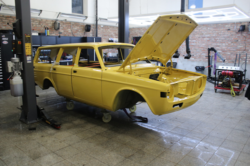
We have assisted in the renovation of this charming Volvo 145 from 1973. The car has been completely renovated and of course, we wanted to be along for the ride. In addition to supplying various parts for the renovation, we also helped with mounting rear and front carriage, headliner and windshield.
→ Front suspension
→ Rear suspension
→ Headliner
→ Windshield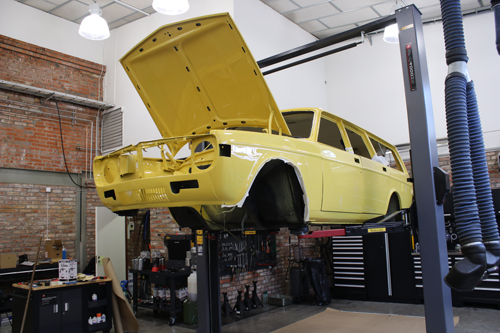
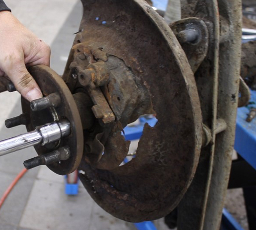
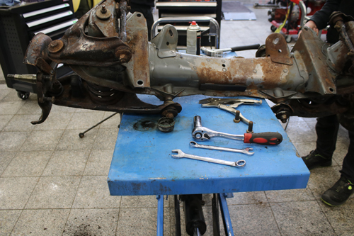
The rear axle looked like this when it was removed from the car. A lot of rust and the brake shields were badly weathered.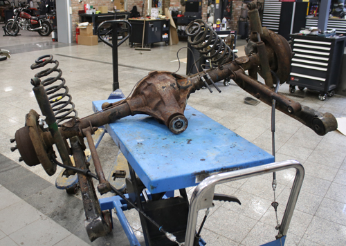
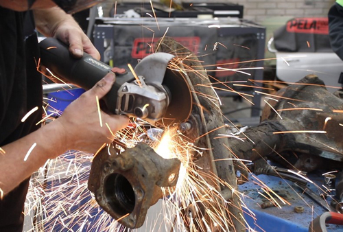
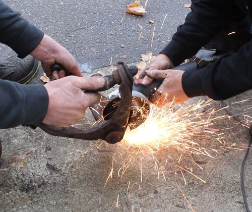
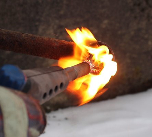
We struggled a bit with removing all the parts from the rear axle and had to use some different methods. We tried heating a particularly stubborn bolt, but it still wouldn't move. We ended up having to cut it off with an angle grinder. Fortunately, we have plenty of new parts available 😉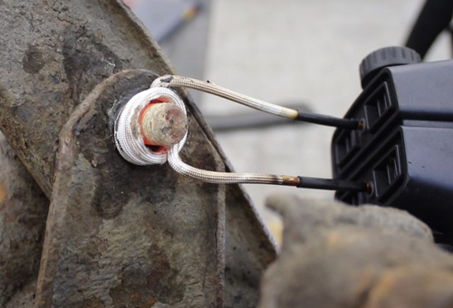
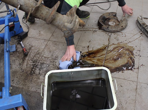
There was certainly plenty of oil in the rear axle, which we noticed when we pried out the drive shafts... Unfortunately, we realized that we should put a tub underneath only after we got the floor covered in oil.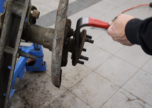
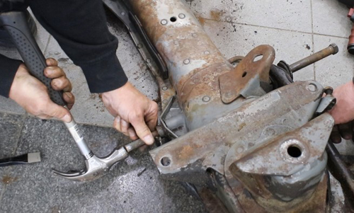
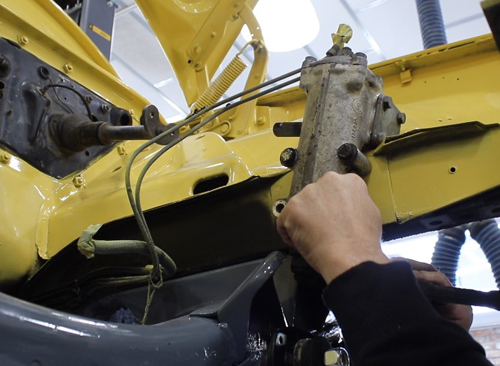
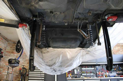
Time to dismount the front carriage. It looked like this when we took it down: 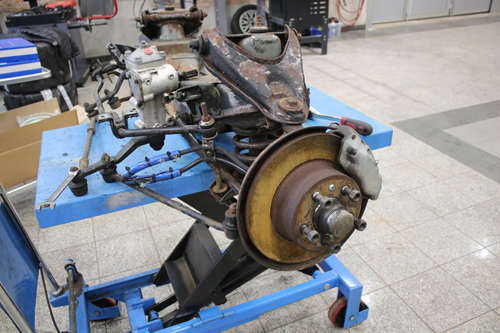
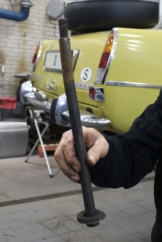
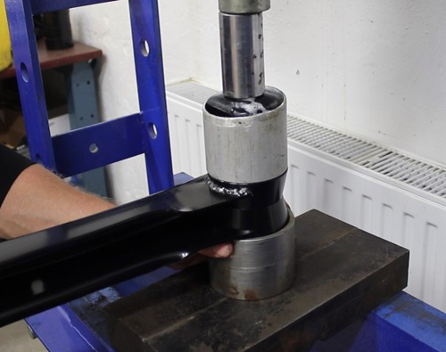
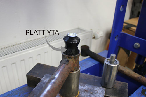
When all the parts on both the rear and front carriage were disassembled, we pressed out all the bushings. We struggled a bit with this also, and had to be creative with different methods. The link arms in particular can be difficult to fit into the hydraulic press, so you may need to be a little inventive to access all the bushings. One bushing was so tight that we had to burn out the rubber. Looks cool on the picture, but not something that is recommended if you get it out in another way.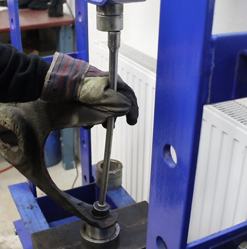

All parts had to undergo a necessary blasting and then get some paint. Fortunately, pressing in the new bushings was somewhat smoother than pressing the old ones out. After a dip in soapy water and with help from a hydraulic press, they slipped in pretty easily. However, make sure that the holes are smooth on the inside so that the bushings can be pressed in unhindered. Some bushings need to be pressed in in a particular direction. Read under the headings for front suspension and rear suspension what is important to consider before pressing bushings into place.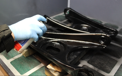
Front suspension
We assembled the parts on the front axle outside of the car to get better access with the tools. We encountered a small problem with the ball joints that are pressed into the link arms, as they would not lock properly. This is something to be aware of, as we have seen the same problem before on these cars. You should not be able to knock the ball joints out of place by hand. We locked them into place by soldering them.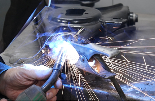
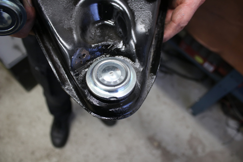
The ball joints in the upper link arms should sit with the recess straight out from the arm, according to the pictures below.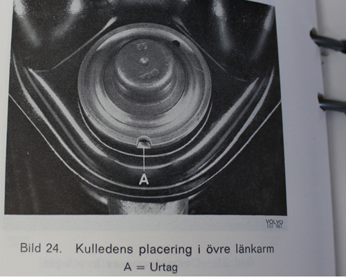
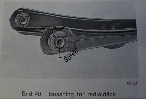
Note! In the lower link arms of early design (until 1969), the bushings should be pressed from the outside, i.e. with the rubber flanges facing in opposite directions. From model year 1970 onwards, which we are working with in this case, both bushings must sit with the rubber flange towards the back of the carriage. One of the bushings therefore needs to be pressed into place from the inside. If radial tires are to be used, the recess in the rubber must also be turned downwards, perpendicular to the longitudinal direction of the link arm. See picture below.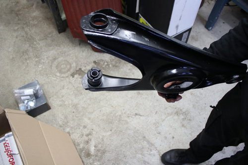
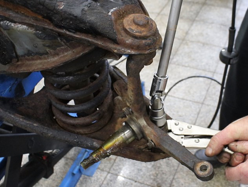
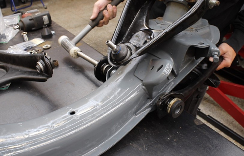
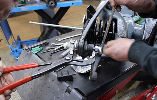
To bring the upper and lower link arms together and attach them to the wheel spindle, the coil spring needs to be compressed with a spring tensioner. We took a little extra help from a pair of polygrip pliers to press the parts together further and get enough room to tighten the nut to the ball joint.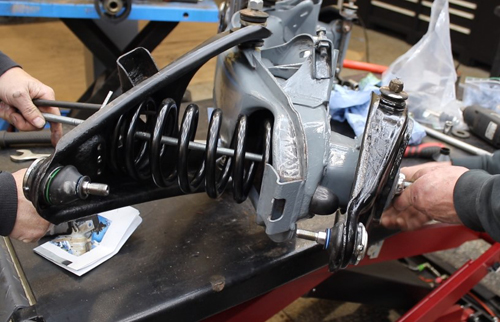
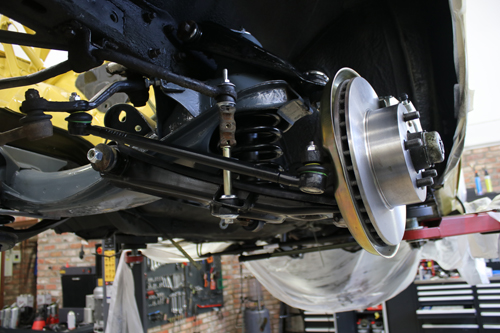
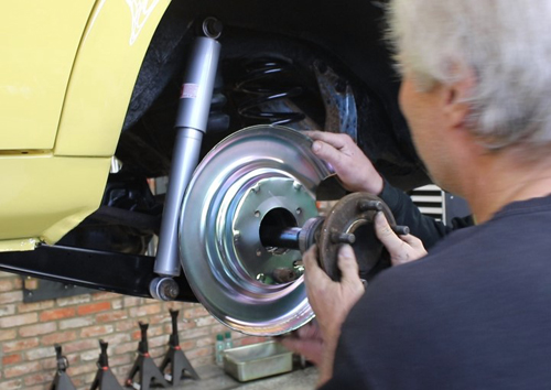
The front axle and it’s attached parts was mounted on the car and a pair of new shock absorbers completed the front suspension once the axle was in place. We also mounted steering rods, sway bar and steering box. 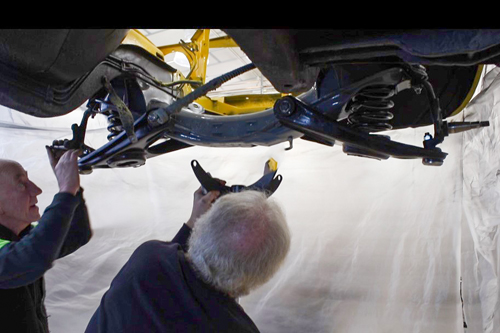
The car also got some brand-new brake backing plates, brake discs and brake calipers while we were at it.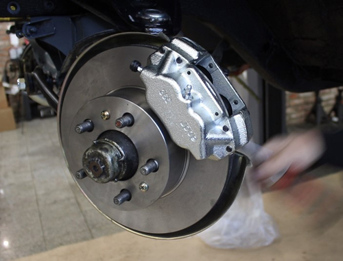
Rear suspension
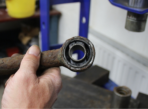
Be aware of how you press the bushings into the support stays. They have two flat surfaces that need to be placed in the correct direction in the hole of the support stay. They can be difficult to see in our pictures but are otherwise easy to see and feel. The flat surfaces must sit straight in line with the arm itself. See picture. 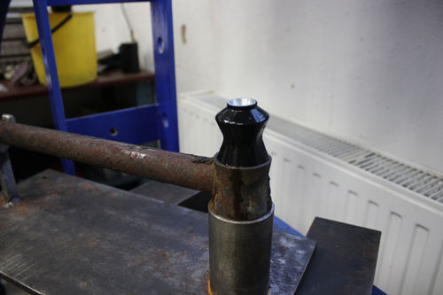
The same applies to the support arms, the flat surface should be straight in line with the arm (first picture below). The right bushing in the anti-roll bar must also sit with the flat part, where the rubber is missing, straight in line with the arm (second picture below). 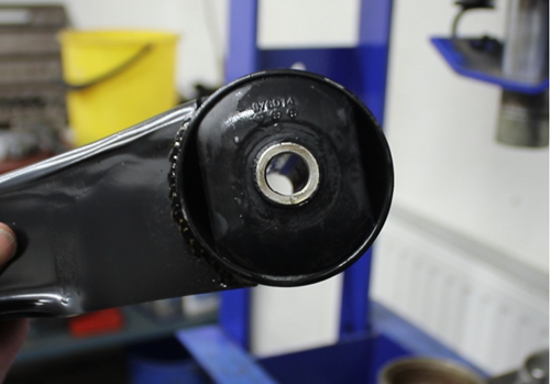
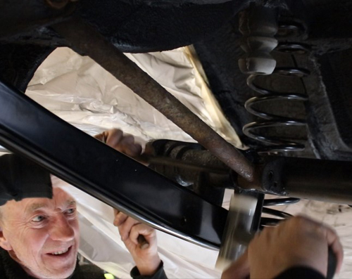
First up were the support arms and support stays. New, fresh coil springs were also put into place.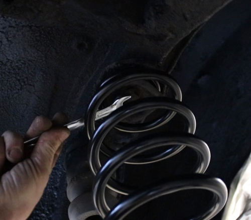
Up with the rear axle! Be sure not to completely tighten all bolts and nuts before everything is in place. For us, it was a bit tricky to get everything to fit perfectly right away. We had to loosen the support stays and arms a bit and knock a little with a rubber mallet to get all parts into the right position.
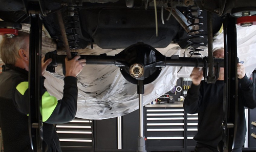
Of course, the car's owner wanted new shock absorbers and brake backing plates because there wasn't much left of the old ones. The wheel bearings on the drive axles also needed to be replaced. We pushed the drive axles in, and the rear axle was complete!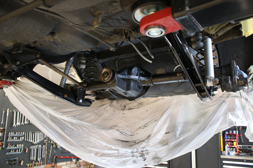
Don't forget to completely tighten all the nuts when you're done!

We at VP were also responsible for the installation of the car's new headliner (art. no. 691866). Replacing the headliner can be a bit complicated and require some patience. Here are some general tips that may help:
- Roll out your new headliner well in advance of installing it. Preferably a day before, so that all folds have time to be smoothed out.
- Consider the temperature. The vinyl is easiest to work with if it is warm. Use a heating radiator to soften the material if it is cold where you work.
- Save your old headliner until you are finished with the installation, to use as a reference during the process.
- Use appropriate tools when attaching the ceiling. With us you will find, for example, these: ITK.
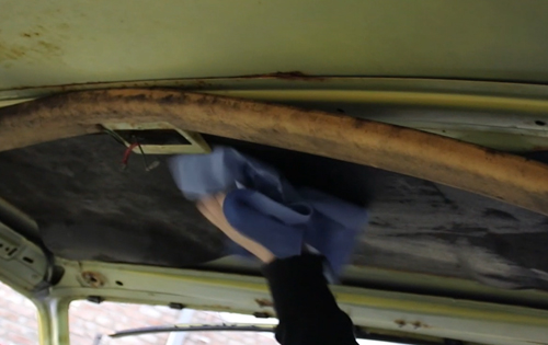
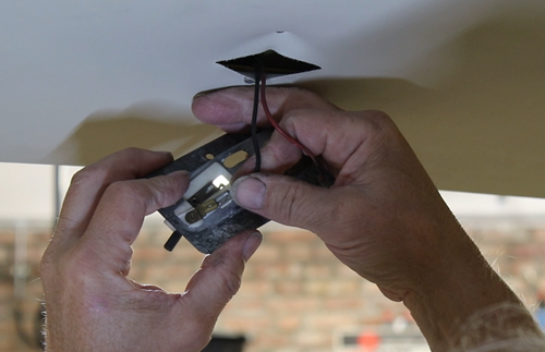
We started by unscrewing all the internal equipment in the ceiling. Here, it is important to directly screw all screws back into their holes. They need to be in place so that you later can feel them through the new headliner. Therefore, do not screw them in too far. Be careful when removing the interior lighting. Note how the cables sit to surely put them back in the same way. The moldings by the windshield were also removed.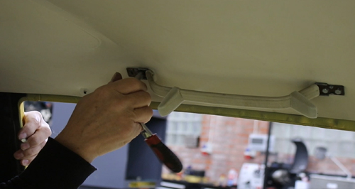
The old headliner was removed, and the roof bows/rails were carefully bent out of place. It turned out to be some mold underneath and we therefore had to clean the ceiling with methylated spirit.
We placed the old headliner next to the new one and moved the roof rails over. Make sure that the bend in the middle points up, so that the roof is tensioned upwards in the car later.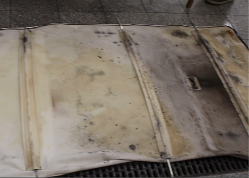
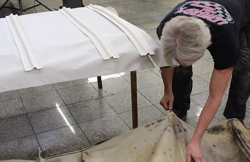
The roof rails, with the new headliner, were carefully bent in above the rail in the ceiling. We measured out the center of the car's roof to be able to match it with the center of the headliner. 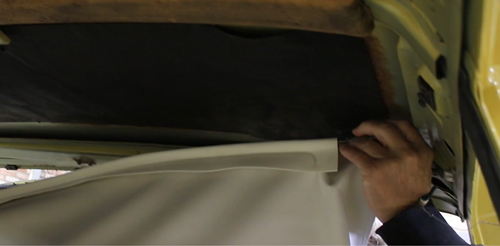
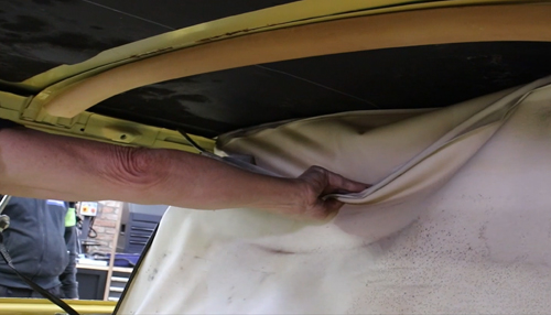
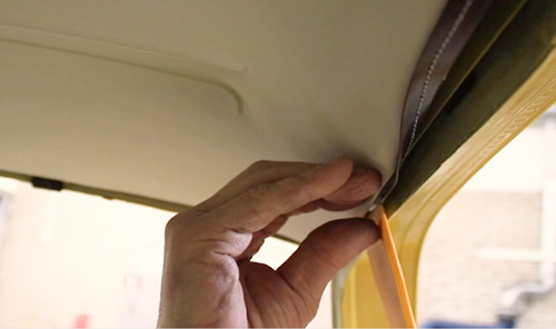
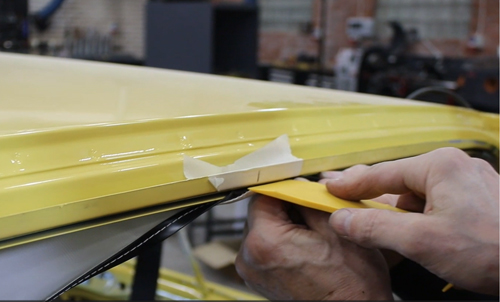
We started attaching the headliner from the front. The vinyl must be folded around the rail with the black strip folded inwards, so that it will not be visible.
When getting the vinyl into the gap between the metal edge and the ceiling, there is little room for your fingers. You can therefore use a tool to poke with to get the headliners molding into the narrow gap. Unfortunately, we had forgotten to bring our own tools, so we had to get creative and found a spatula in the workshop to poke with. However, be careful that the tool is not sharp or for other reasons can damage the headliner. You will find suitable tools in our kit ITK.
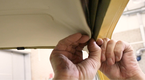
To get the headliner straight and even, we worked in parallel with both sides and took a little bit at a time on each long side. We needed to gradually pull the headliner back to get enough material towards the end. When you pull the headliner, you need to make sure that the roof rails do not get stuck on anything and thus prevent the headliner from moving backwards.
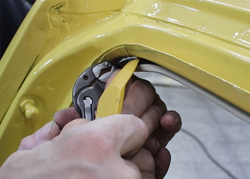
The end is the most difficult part as it is tight with material to get around the last corner of the rail. We used pliers to get hold of the corners and be able to pull the headliner back a little further. Note! If using pliers, pinch the black strip to avoid damaging the vinyl.
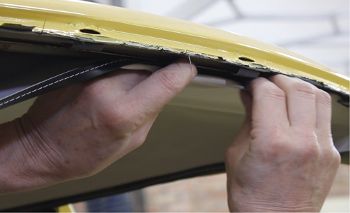
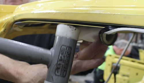
Another problem we encountered was that the metal rail had become warped at the back of the car. The gap had become too wide, which meant that the headliner would not stick. We solved this by lightly hitting the metal rail with a rubber mallet, to make the gap tighter.
The headliner was finally fixed all around the ceiling and it was time to attach all the interior details again. But first we had to locate all the screws underneath the headliner. Holes were cut for the screws, and we then screwed back the handles, sun visor, rearview mirror, etc. The moldings by the windshield were also attached.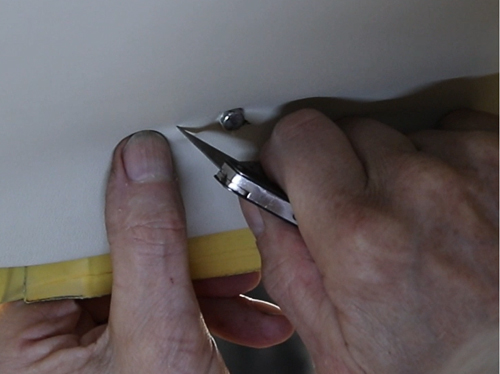
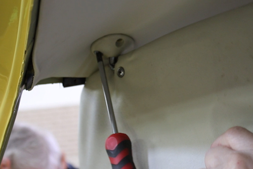
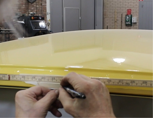
We had a little trouble locating cables and screws for the interior lighting. We solved this by comparing where the holes were made in the old headliner and simply measuring the correct position with a ruler.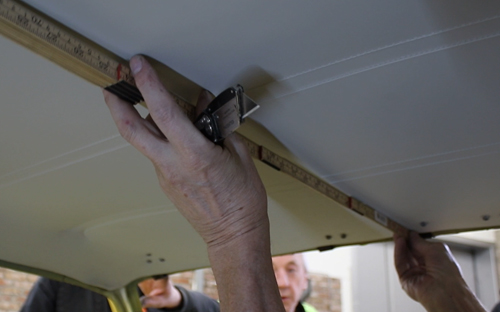
Done! See the entire process on video below. 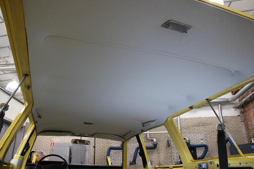

Windshields can be installed using several different methods. On this Volvo 145 of later design, the windshield (675831) is attached with butyl tape or glue specially made for windshields. We used glue. ATTENTION! Improperly installed windshields can be a safety hazard. Therefore, get help with mounting your windshield if you are in the least unsure of how to get it to attach properly.
This is how we did it:
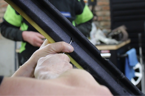
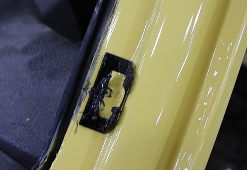
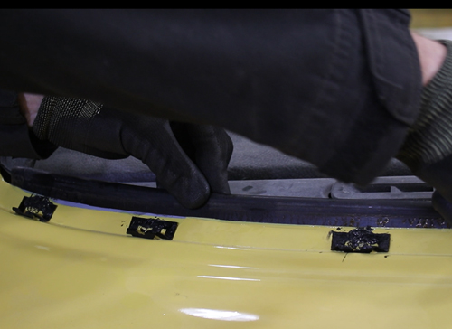
There are holes in the bodywork around the position of the window, in which clips for the trim molding (682321) are to be mounted. We started by spraying sealant into these holes. Then the 23 clips were attached, and sealant was also applied over the clips. It is important that the holes get completely sealed, otherwise water may leak in later. 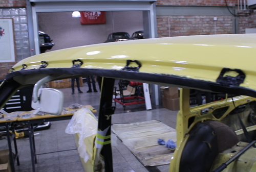
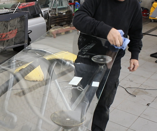
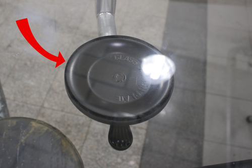
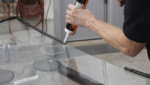
We attached suction cup handles to the windshield. They should be attached to a surface as flat as possible, surfaces where the window bulges slightly outwards are difficult to attach the suction cups properly to. When you can see that a darker black ring has formed at the edge of the suction cups, they are firmly attached (see picture). 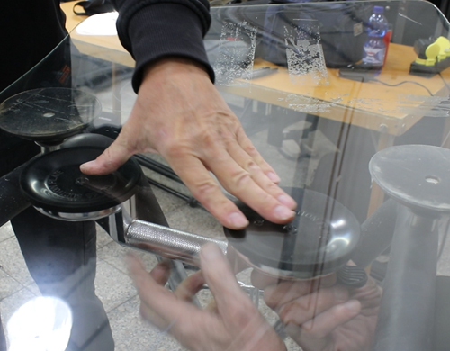
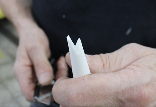
The glue used must be specially made for attaching windshields. You should also review the manufacturer's recommendations for how long it then needs to dry. We cut the nozzle on the glue container with a knife to make it angled. We wanted to make the nozzle tip a "V" with one side slightly longer than the other (see picture).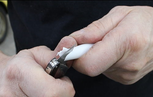
The glue was applied along the edge, all the way around the windshield in one go, without lifting the container. If you lift the container or make a stop, there is a big risk that air bubbles will form or that it will be uneven.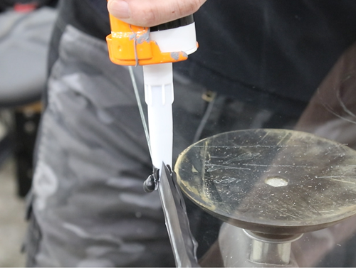
Lifting the window into place is a two-man job. We carefully put the windshield into place and made sure it was correctly positioned, not lying directly against any of the clips. To prevent the windshield from sliding down before the glue had dried, it needed to be fixed by being supported from underneath. We used foam rubber because it was close at hand, but as long as it serves its purpose, the material is of less significance. 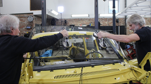
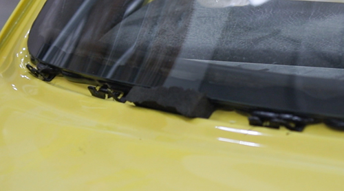
The trim molding of the windshield is attached by pressing it down between the clips and the body of the car. Unfortunately, we did not capture any pictures of this process, but we initially pressed down the lower trim, with a corner joint attached. Next, we mounted one side trim with a corner joint. The other side trim, the upper trim, and the two remaining corner joints were attached to each other and then mounted as a whole. This was done to make the fitting easier.